Step-by-Step Instructions
1. Connecting the Device:
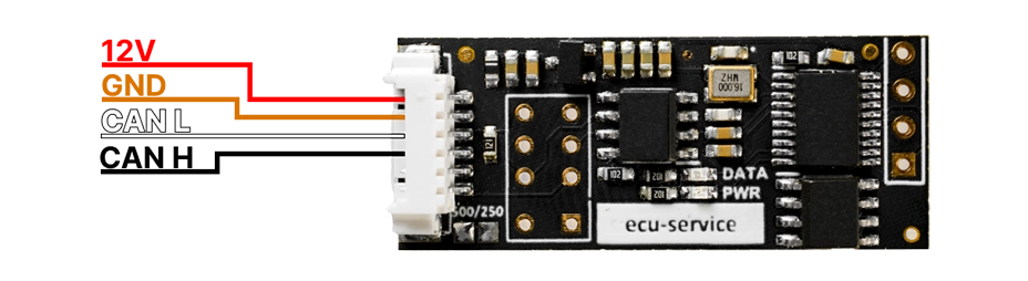
- Connect the CAN-SENDER to the power supply in the vehicle or on the test bench.
- Ensure that all wires are properly connected to the CAN bus.
2. Selecting CAN Speed:
- Go to address 0x00 to set the CAN speed.
Enter :
- 0x00 for 125 kbps.
- 0x01 for 250 kbps.
- 0x02 for 500 kbps.
- 0x03 for 800 kbps.
3. Configuring CAN Frames:
00 00 00 11
0
8
11 22 33 44 55 66 77 88
FF FF
01
- Frame ID
- 0 – standard frame, 1 – extended frame.
- Data length (0-8 bytes).
- Data: Enter the corresponding data values.
- Time interval (e.g., how often the frame should be sent).
- Cycle count: How many times the frame should be sent.
4. Monitoring LEDs:
- Red LED blinks, green LED off: CAN speed error or improperly soldered EEPROM memory.
- Red LED on, green LED off: No data entry to send.
- Red LED on, green LED blinks every 800ms: Data is being sent correctly.